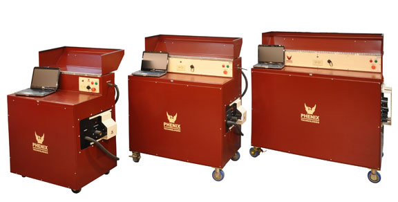
Excessive core loss negatively affects the efficiency and reliability of a motor. Core loss testing is necessary to insure the quality of a motor or motor rewind. The Phenix Technologies Core Loss Test Set is a continuously variable low voltage, high current power supply for testing stators, rotors and armature cores.
Unique design features include:
- True sine wave output ensures test results that are both accurate and repeatable.
- User-friendly software guides the operator through the test sequence--Automatically ramps up the voltage, records the results, calculates and ramps the voltage back down.
- The duty cycle allows the operator to overexcite and heat the core sufficiently to locate hot spots.
| Models Offered and Approx. Max Testing Capability | |||||
| CL10A | CL25A | CL60A | CL125A | CL300A | CL500A |
| 500 HP | 1,250 HP | 2,500 HP | 5,000 HP | 12,00 HP | 20,000 HP |

SAFETY and DESIGN FEATURES DESCRIPTION PHENIX
ENEFITS OF CORE LOSS TESTING
The Phenix Technologies Core Loss Test Set is a continuously va riable lowvoltage, high current power supply for testing stators, rotors, and armaturecores. These units have very low distortion, independent of load and outputsetting. This insures test results that are both accurateand repeatable. Thebasic test set includes complete instrumentation; output an d voltmeter cables,computer and printer. The computer is used for complete control, metering, datastorage and evaluation of test results. Operation of the test set is as easy ashooking up the test leads, typing in the parameters of the test and pushing abutton. The test set takes over from there; automatically ramps up the voltage,records the results, does all the necessary calculations and ramps the voltageback down. The automated function eliminates operator error; severalpre-programmed messages will alert the operator of test set up errors, savingtime and increasing operator safety. A database can be built for spe cific motorstested. Past results can be easily accessed when re-test ing a motor that hasbeen tested in the past, making trend analysis q uick and easy.
The operating software interfaces with the test sets Programmable Logic Controller(PLC) that in turn guides the test set through its test functions. The PLCeliminates a large portion of circuitry required in man ual test units. Withless circuitry, the test set becomes much more reliable and easier to troubleshootif a problem does occur. Precision control of the output setting is possiblewith 3-5 ra nges per output tap. This translates into 3-5 times greaterregulation of the output
voltage setting. A meter calibration is done through the computer; savingtime a nd insuring accurate readings. There is no need to remove panels off thetest set to calibrate the metering.
The duty cycle allows the operator to overexcite and heat the core sufficientlyto locate hot spots.
• Main power circuit breaker
• Fused power control circuits
• Emergency Off pushbutton
• Multi-range digital meters
• External interlock provision
• Continuously variable output
• Thermal overload protection
• Output is controlled by a motorized voltage regulatorwith variable rate of rise
• Output cables for stator testing
• Internal, external, and transient overload protection
• Zero-start interlock
• Rugged steel cabinet
• Casters, lockable cover, and storage hook (CL10A,CL25A, CL60A, CL125A)
• Separate voltmeter leads for greater metering accuracy
• Two copies of Operation/
Maintenance manual
The function of a core loss test set is to determine whether a motor hasdamaged
core iron. Damage could include shorts between laminations and damagecaused by winding failure. A vital step in the rewinding of a motor isperforming a core loss test before the windings are removed to detect anydamage to the core. After
the windings are removed, the core should be re-tested to verify that itwas not damaged during removal of the old winding. Although it is possible fora motor to still run with core damage, the efficiency of the motor will begreatly reduced. The motor will consume more power to operate at normal levelsand it will cause the motor to generate more heat. Heat will in turn reduce thereliability of the motor and its overall functional life. An increase of 10°C in the winding can reduce thermal insulation life by half. All of theseconsequences add up to more operating and maintenance cost and loss ofproduction time.
