


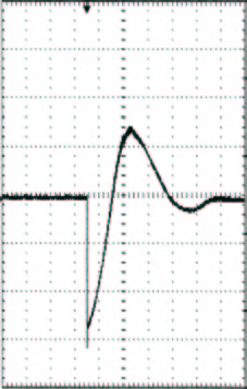
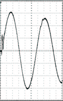
...because "PJ" is the only manufacturer --> --> Other manufacturers make Impulse Testers! Since 1969, the PJ Electronics High Frequency Surge Tester was the only tester of its kind then, and still is today. The basic technology of an impulse tester has been copied throughout the world, but our unique High Frequency Technology has not. A PJ High Frequency Surge Tester is not only a Quality Surge Tester for testing turn-to-turn insulation for coils, but it can be used for all of your electrical motor testing. (1) Resonant Current Waveforms for Surge Testing "coil-to-coil" and low impedance windings. (Figure on right)
| |
|
-->WHAT'S THE DIFFERENCE BETWEEN AN IMPULSE TESTER AND A PJ HIGH FREQUENCY SURGE TESTER?
In our High Frequency Surge Testers, coils are pulsed with high capacitor discharge energy that results in a resonant circuit with the coil under test. This test procedure enables the low impedance coils to support high surge voltages by being an integral part of the resonant circuit. PJ Testers cause the load to resonate with the source energy discharge capacitors by being built into a series resonant circuit. The unique feature to our High Frequency Surge Testers is the employment of a bi-directional switch. This switch permits the load coils to resonate with the discharge capacitors, that result in stressing of the coils both in the forward and reverse direction with voltage stressing both positively and negatively during each oscillation.
In an impulse tester, which is employed in all of our competitor's testers, a uni-directional voltage pulse is discharged into the coil under test. This pulse energy causes the coil to resonate only within its natural frequency. This natural coil resonance results in dissipating the pulse energy that was initially applied to the coil. When Impulse Testing, it is very difficult, if not impossible, to establish turn-to-turn voltage distribution when it is subjected to a unidirectional pulse as from an Impulse Tester. Depending on the coils internal distributed capacitance, the pulse voltage will be separated in a non-uniform manner. An Impulse Tester (all competitors) does not permit the coil voltage from oscillating below ground when the pulse voltage is only positive in nature. When coils are subjected to this impulse test, there is no practical way that one can actually verify what this turn-to-turn insulation is seeing.
Our High Frequency Technology is superior to Impulse Technology for surge testing / stressing insulation because we use a Bi-Directional Switch and not a Uni-Directional Switch. Our Voltage Rise Time is 0.1 micro-seconds (0.1 x 10 to the (-6) or 0.0000001 seconds). This means that when our applied surge voltage is across the coils under test, it will take 0.0000001 seconds for any PJ High Frequency Surge Tester to change from 10% to 90% of our maximum applied test voltage. For example, it would take our 50KV PJ High Frequency Surge Tester 0.0000001 seconds to deliver an output voltage from 5,000 Volts to 45,000 Volts. Our Voltage Rise Time is fixed at 0.1 micro-seconds throughout the surge tester's entire output voltage range. In addition to our Bi-Directional Switch and our fixed 0.1 micro-second voltage rise time, all PJ High Frequency Surge Testers pulse and resonate with the coils under test at 60 Pulses Per Second (60pps @ 60 Hz. and 50 pps @ 50 Hz.). Within each and every pulse, our high frequency discharge energy is cycling and resonating throughout the coils, stressing the coil's turn-to-turn insulation in the forward and reverse direction. After this high frequency burst of energy, the surge tester recycles and regenerates another pulse of high frequency energy every 16 milli-seconds (0.016 seconds). These high frequency bursts of high surge energy continue to stress each and every turn of the coil�s insulation unlike no other surge tester on the market today or for the last 40+ years.
PJ High Frequency Surge Testers outperform all Impulse Testers due to their Uni-Directional Switch Technology, Variable Voltage Rise Times as slow as 2.0 micro-seconds on coils and a repetition pulse rate as slow as 1 impulse every 2 seconds (0.5 Hz.). The impulse energy does not resonate with the coils, just shocks them and dampens out by way of the natural frequency of the test coils.
![]()
<!--
-->
TESTING AC ROTATING ELECTRIC MOTORS
When testing phases of a motor, no tester, including our PJ Surge Tester, will uniformly stress the turn-to-turn insulation of every coil in the phase of disassembled or assembled motors. This is why it is imperative to surge test each and every coil prior to installing the coil into the motor. As we stated many times before, there is no better method of checking /stressing the integrity of the coil than with a tester with High Frequency Technology.
But what if you cannot test the coils prior to installation? What if you only have a multi-phase motor to surge test with the rotor removed? Finally, what if you have to surge test a fully assembled motor? All of our competitors claim that they are capable of surge testing multi-phase motors, but they have never explained how the voltage is being applied to the coils in the phases. You may believe that an Impulse Tester can test 3 phase motors, but what do you think it is detecting?
Every PJ High Frequency Surge Tester is capable of effectively surge testing grounded or ungrounded Fully Assembled Motors without moving the position of the Rotor.
Since our discharge energy is continuously resonating at 60pps, every cycle of our surge energy is constantly recycling the resonant current and resonant voltage back and forth to our capacitors. The surge energy is contained with high power levels to work through those windings in each phase with sufficient energy and still have the capacity to detect defective insulation.
An explanation on how our competitor�s voltage is being applied to the coils in multi phase motors. Our surge voltage differs drastically from that supplied by standard impulse testers. Most impulse testers have a pulse repetition rate of 5 pulses per second, i.e., one every 200 milliseconds. When an impulse tester is discharged into a motor winding it contains one and only one burst of energy in which the energy slowly dissipates to zero. The motor is not subjected to another energy burst until a time period of 200 milliseconds has elapsed. When it surges the windings with its relatively slow rate of rise, it gives an unequal distribution of the voltage across the entire phase in only one direction. In a one second time period, the impulse tester subjects the motor windings to 5 and only 5 bursts of surge energy whereas as the PJ Surge Tester will have subjected the motor to 60 high frequency bursts of energy. However, each of our high frequency bursts consist of a decaying oscillation of approximately 5 cycles of energy pulses that gradually dissipates to zero. Under these conditions, the motor would be subjected to 300 energy pulses during the same time period in which the impulse tester would have delivered 5 pulses of energy.
An Impulse Tester does not have the voltage risetime or duration of repetitive peak discharge energy during the unidirectional discharge time period to effectively stress weak turn-to-turn insulation in a single coil, not to mention an entire phase!
![]()
![]()
HOW TO SELECT A PJ SURGE TESTER
(2 X Rated Line Voltage + 1000) X 1.414
For example, to surge test a 4160 volt AC Motor, you would multiply the line voltage (4160) by 2 to get 8320, then add 1000, the sum would equal 9320; then multiply this number by 1.414 to obtain the surge test voltage. This test voltage would equal 13,178 volts. Any one of our 15 KV Models would be able to perform this test.
All P J Surge Testers are capable of testing DC Armatures. A special tester is not needed!
<!--
We added a new armature feature on certain model Testers. All Bench models and Console Models up to 15KV (no Portable models), are equipped with a new armature feature. We now manufacture these models with a high voltage rotary switch to permit the tester to operate as either a low inductance Armature Tester or a standard Surge Tester.
-->DC armature testing is accomplished by an Armature Test Yoke Assembly (ATYA) that conveniently applies the test surge voltage to the armature coils via the commutator segments. By providing a proper yoke set-up for supporting the armature and using the three spring-loaded contact fingers for commutator connections, as shown in the picture, the operator can manually rotate the armature and observe the oscillographic wave pattern. Thus, one section of the armature is constantly being compared to a new section of the armature under test. A good armature can be tested in this way in only a couple of minutes by a single operator.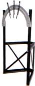
Some of our competitors limit the applied bar-to-bar test voltage to only 900 volts. With a PJ Surge Tester, there is no restriction in the magnitude of the applied bar-to-bar voltage. We have had customers inform us that they are testing D.C. Armatures at 1250 to 1500 volts bar-to-bar and they are now uncovering defects that they normally would not have detected at the lower test voltages. By detecting these defects during the test phase, they were able to eliminate costly motor failures in the field.
FACTS REGARDING CALIBRATING TESTERS...<!--![]() -->
-->
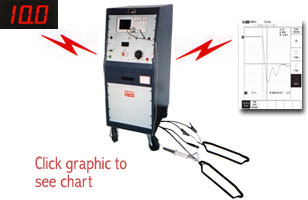
All P J Surge Testers indicate the value of peak output voltage on a large digital panel meter that is accurately calibrated to be the actual voltage that is applied across the test coils. Our calibration accuracy is Traceable to NIST. Our customers can actually verify the output voltage, as displayed on the panel meter, for themselves at any time. This is accomplished by using an optional calibrated High Voltage Probe in conjunction with our Digital Oscilloscopes that we supply with every one of our testers. This test procedure can be seen by the illustration shown below:
We challenge our competition to prove their output voltage under any low inductance load, at any time! None of our competitors explain, illustrate or prove their output voltage. Impulse testers severely regulate under low inductance loads and their output voltage displayed on the meter is not the same across the coils. Don't let our competitors insult your intelligence by claiming that they have a "button" to self calibrate their surge testers. Some of our competitors just calibrate the meter movement on their testers or adjust the gains on their oscilloscopes. We calibrate our PJ Surge Testers under actual load conditions throughout the testers entire output voltage range. Future calibrations on all PJ High Frequency Surge Testers should be performed at our factory to conform to NIST. If calibration is performed elsewhere, the calibration agency must employ procedures as recommended by PJ Electronics, Inc.
![]()
DIGITAL REAL TIME OSCILLOSCOPES, USB STORAGE, PRINTING, ANALYSIS,...ETC.
All P J High Frequency Surge Testers currently come equipped with a high performance color Rigol DSE series storage, programmable oscilloscope with USB Interface Ports, Software, multi-language user interface and a bonus USB Flash Drive for unlimited storage capabilities. These scopes include a USB host port for removable data storage support and USB device port for either PC connectivity or direct print capabilities. It offers a maximum Sampling Rate of 1 GSa/s which provides accurate real-time acquisitions, 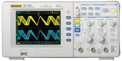 <!--
<!-- -->the opportunity to freeze, store, save/reference and measure waveforms "on screen" for analysis. The digital scopes are all "user-friendly" with on screen menus, traditional buttons and knobs which retain analog simplicity yet gives quick access to the wide range of digital functions. Every oscilloscope is pre-programmed at P J Electronics before it leaves our factory, so that the settings are correctly positioned and ready to display the bright and vivid waveforms on a color liquid crystal display (LCD) screen. You can also pre-program up to 10 different scope set-ups to enable you to quickly get proper waveform patterns for various testing applications. You may also view the scope in one of 10 different languages: English, Spanish, French, German, Russian, Portuguese, Korean, Japanese, Traditional Chinese or Simplified Chinese. In addition, these "state of the art" oscilloscopes offer a 3 year warranty.
Rainbow of COLORS. As described above, all of our Model Testers are now equipped with a Rigol color oscilloscope. The color makes it easier to distinguish good and bad waveforms because channel 1, channel 2, and the reference waveform are in different colors.
Everything that is displayed on the colored Oscilloscope may either be printed out, displayed on the PC via the software and/or stored on the USB Flash Drive in color, exactly as it appears on the scope.
Do more with your waveforms with the new Standard Features. All Oscilloscopes come standard with an accessible front-panel USB host port for an easy way to save data onto the included USB Flash Drive. ![]()
 Use the USB Flash Drive to store, reference, identify and recall virtually an unlimited number of waveform data. Once you have loaded the USB Flash Drive with waveform data, you may download the data on various PC formats for analysis (some formats listed below). (NOTE: No additional software is required when you save waveform data on the USB Flash Drive).
Software included at no additional charge.
The Rigol Scope offers UltraScope software. It provides quick and easy capturing and saving of waveform data and images directly onto a PC (Microsoft Windows Compatible). Truly seamless PC connectivity via a USB device port / USB Plug-and-Play. The software provides the ability to generate reports with Microsoft Word, Excel, Outlook, PowerPoint and WordPad, as well as, with stand-alone desktop application. The software provides live waveform analysis, remote control of oscilloscope and extended analysis capability.
Innovative direct print capability. Print directly from the oscilloscope to printer with the push of one button, using our optional Canon Pixma PictBridge� Printer. This high resolution printer is connected to the oscilloscope, stored and mounted in the custom panel sliding drawer of our Console Models (or connected and secured on top of our Portable and Bench Models). The printer will print everything that is seen on the scope's display screen.
These removable oscilloscopes can also be used for trouble shooting motor controllers, power supplies and other electronic circuitry. Most importantly, they can be used to verify the peak output voltage of the test coils, at any time you wish (using a high voltage probe, contact us for details).

Type: Our Complete Line of 我们的完整产品线 | |||||||||||||||||||||||||||||||||||||||||||||||||||||||||||||||||||||||||||||||||||||||||||||||||||||||||||||||||||||||||||||||||||||
| |||||||||||||||||||||||||||||||||||||||||||||||||||||||||||||||||||||||||||||||||||||||||||||||||||||||||||||||||||||||||||||||||||||
| 技术规格:
|
| |||||||||||||||||||||||||||||||||||||||||||||||||||||||||||||||||||||||||||||||||||||||||||||||||||||||||||||||||||||||||||||||||||
|
|
| |||||||||||||||||||||||||||||||||||||||||||||||||||||||||||||||||||||||||||||||||||||||||||||||||||||||||||||||||||||||||||||||||||