
MYG-RSO Detect technology:
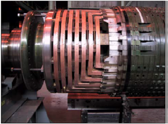
Largehigh-speed electrical generators use a rotating magnetic field produced by acylindrical rotor in the form of a electromagnet having either 2 or 4 magneticpoles. The rotor body is a solid steel forging containing radial slots for thecoils which make up the electromagnets (rotor windings).
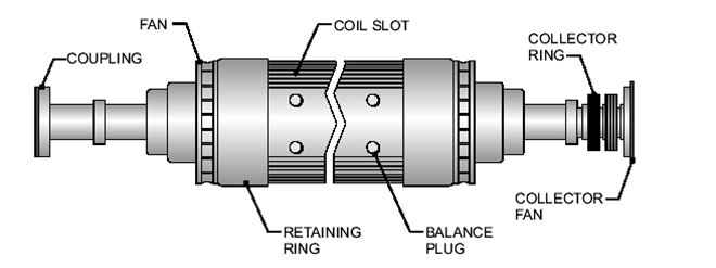
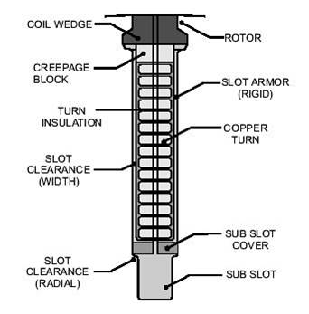
Theturns of the coils are rectangular copper bars, insulated with an epoxymaterial and in a 2-pole rotor, there are typically 8 pairs of slots for eachpole of the electromagnet.
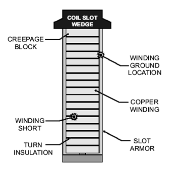
Eachwinding slot contains up to 20 conductor turns. The figure shows across-section of a typical radial slot (in this case, containing 15 turns ofinsulated copper bar).
Atthe ends of the rotor body, the turns pass from the end of one slot to itsequivalent slot on the other side of the magnetic pole and are held in place inthe end regions by steel end rings. A direct current of around 3000 amps flowsthrough the rotor winding to produce the magnetic field, which is atright-angles to the axis of rotation, with clearly-defined north and southpoles.
Generatorrotors are routinely tested to detect these types of fault, usually duringconstruction and also before routine generator maintenance.
Onestandard test method used is based on the use of time-domain reflectometry(TDR), and is based on the methods used by telecommunications engineers tolocate faults on telephone and data network transmission lines.
However,unlike the technique used for testing transmission lines, the rotor winding isa very imperfect transmission line and produces a large number of reflectionsat each change in impedance between the sections of conductors inside the radial slots and thesections in the cross-over end regions. This makes it virtually impossible toidentify rotor winding faults by simply observing the TDR waveforms.
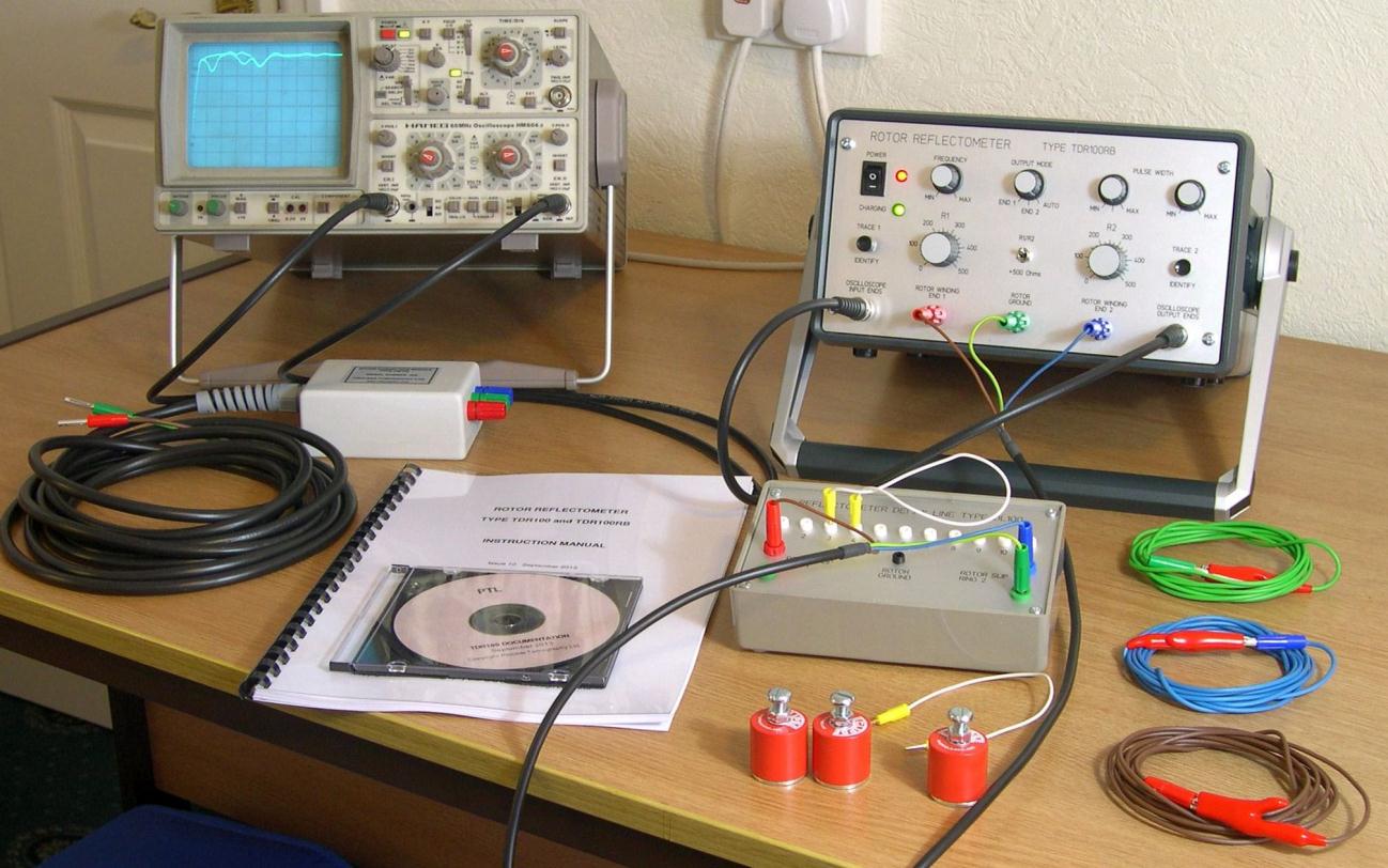
Consequently,a modified version of the TDR method must be used with rotor windings. A customtest instrument (Rotor Reflectometer) isused to carry out this test, which is known as the Recurrent Surge Oscilloscope(RSO) method by Power Engineers.
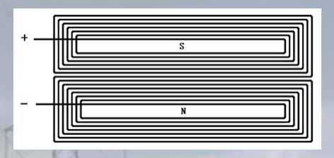
TheRSO test method overcomes the problem of multiple reflections within the rotorwinding. It can detect and locate earth faults or shorted turns in rotorwindings and relies on the fact that the rotor winding is symmetrical. Forexample, a 2-pole rotor contains two nominally-identical half-windings, one forthe North pole and the other for the South pole, both of which are connected inseries as shown above. A four pole rotor is similarly symmetrical.
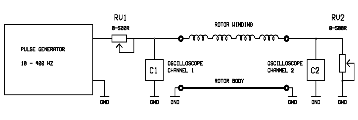
Thissymmetry property is used to compare the response of the 2 halves of the rotor winding to a voltagepulse applied between each slip-ring and the rotor body. The pulses and anyreflected signals are monitored at each end of the rotor winding using anoscilloscope. If the rotor winding is fault-free, two identical waveforms willbe observed at each slip ring. However, if one half-winding contains a fault,the two waveforms will differ.
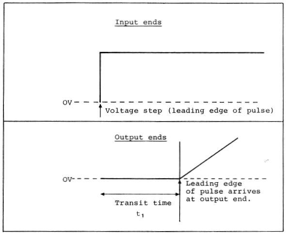
A(typically) square wave pulse (12V) is applied between one of the rotor sliprings and ground and the transmitted pulse received at the remote end of therotor and the reflected pulse at the sending end are monitored.
Thepulse takes a finite time (the transit time) to travel from one end of thewinding to the other and emerges at the far end as a slowly rising ramp becauseof distortion effects in the winding.
Simplified(and idealised)versions of these waveforms are shown above.
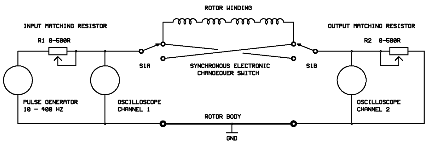
Inpractice, the TDR100testinstrument has a switching circuit which applies pulses alternately from eachend of the rotor winding so that the waveforms are automatically superimposedwhen viewed on a single channel oscilloscope.
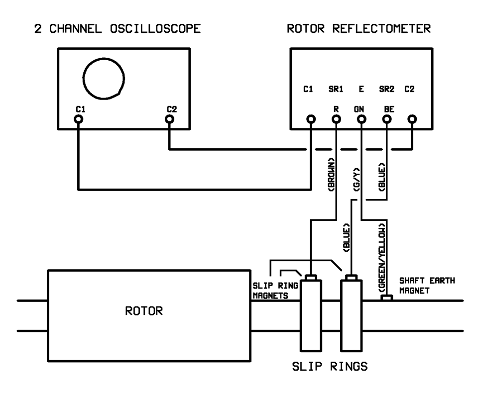
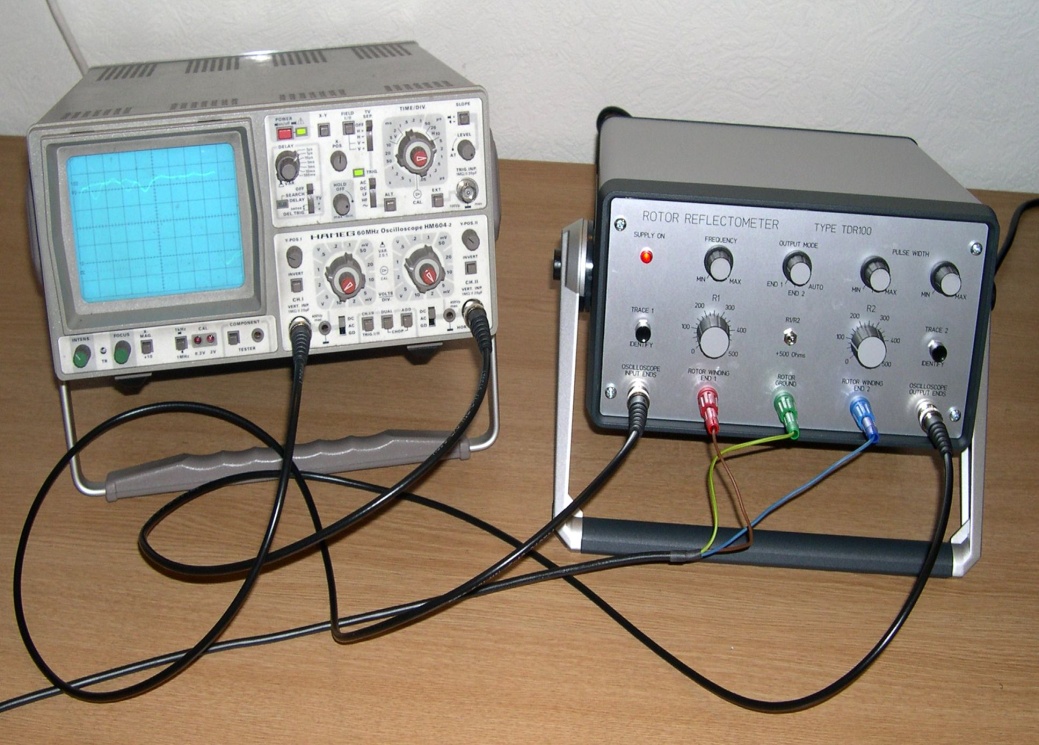
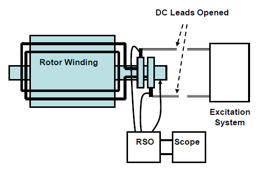
Atypical measurement arrangement is shown above and in the next slide andassumes the use of a basic two channel analogue oscilloscope, although a singlechannel instrument will suffice if a 2-channel oscilloscope is not available.
MYG - RSO interturn short-circuit analyzer generator rotor parameters
N: is suitable for the diode or quadrupole hidden large steam turbine generator rotor interturn short circuit testing;
N: the UK the central electricity board (CEGB) 1973 of the original technology,
N: brand: MYG - RSO, two kinds of specifications:
N; TDR100RB apply voltage 110 or 220 vac, application range of 90 ~ 120%, need to match the oscilloscope for testing
N; TDR200RB applied voltage 110 or 220 VAC, application range of 90 ~ 120%, and a corresponding software and can be tested in the computer display.
N: surge protection, long wave technology, repetitive pulse 1000 / time, automatic calibration function.
N: 50 hz or 60 hz
N: 12 volts peak output voltage 12 V, rising wave width adjustable 20 us - 400 us H: n size: W: 305 mm to 152 mm D: 355 mm
N: weight 5 kg
N: with nickel batteries and lasts for 15 hours
Test pic and Connection
with Fault in the Rotor without Fault In the Rotor
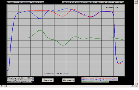
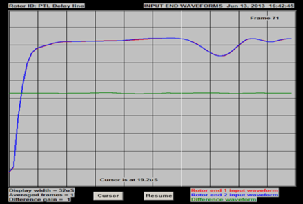
The obvious advantages compared to other brands: 1. Origin: the UK, the RSO technology granddaddy British technology. Originated in Britain the central electricity board (CEGB) 1973 original technology research, it has successfully applied in Britain and around the world for more than 40 years. Technology is very reliable, and the application results and have many users.
2. The use of alternating pulse, the pulse alternately repeatedly into the ends of the generator rotor winding coil. Through an electronic switch, the pulse repetition rate can reach 1000 times per second. Pulse waveform and pulse waveform automatically generated, other brands need to manually adjust.
3. With the calibration function and can automatically, without the skilled personnel will not wrong operation. Other brands need to manually check, error prone.
4. Long wave technology to prevent the signal attenuation on the old unit too fast, 12 V, 12 volts output voltage peak rising wave width adjustable 20 us - 400 us.Other brands use short-wave, if you use a short wave, in some rotor winding, especially some old units or hydroelectric units sudden pole rotor, it can lead to serious attenuation, less reliable.
5. Bring nickel battery, sustainable use 15 hours, and the surge protection function.
Main configuration listing
1, TDR100RB host (built-in battery)
2, the oscilloscope
3, packing suitcase Unit
4, DL100 reflectometer delay line test
5, delay line
6, 3 x 5 m single core (brown, green, blue) 4 mm insulation Banana plug (red, green, blue) (containing connection module)
7, 2 root BNC coaxial cable oscilloscope
8, contact the magnet
9, 3 links rotor test thread
10, the operating instructions
11, certificate of origin
