

- Introduce
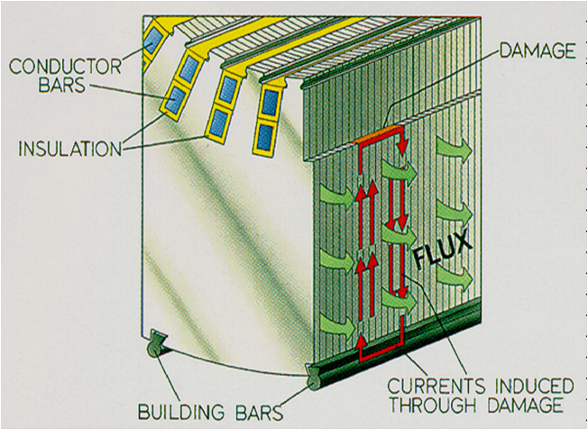
The stacked coreof any generator or motor is made up of separate laminations typically lessthan a millimeter thick, insulated from each other over their surface butfrequently shorted together at the back edges by support bars. This design methodreduces core eddy currents, thus avoiding unnecessary power loss, but dependson the effectiveness of interlamination insulating materials. In order to keepcore length as short as possible and magnetic density high these insulationlayers or coatings must be very thin.With a large number of laminationsthere is a high probability of insulation breakdown. Single shorts between two laminationsmay not be too serious but with several shorts along adjacent layers the faultcurrents induced can be large and cause excessive local heating. Sometimes thisheat cannot be dissipated adequately by local cooling causing more inter laminarfailures. If not detected and repaired at an early stage, faults could inextreme cases burn insulation and melt laminations, requiring the replacementof sections of the core structure, or at earlier stages at least a partialstator rewind. Periodic core inspection is therefore a crucial part of any maintenanceor fabrication programme to avoid excessive break down costs.
- TEST METHODS
A traditional method of detectingfaults is the High Flux Ring Test, often referred to as a Thermal Loop Test.The rotor is removed from the machine and the stator core magnetically energizedby a high voltage high current excitation winding. The magnetic flux producedfollows a single path circumferentially around the core, rather than the rotatingsplit path of the flux induced by the rotor field, but with substantially thesame voltage generated along the core and associated heat from faults. Hot spotsare detected by a variety of means including thermal cameras.The Thermal LoopTest has long been used as an effective tool. However the required degree ofdismantling of the machine, together with the requirement for the high voltageexcitation winding and associated high power source and safety requirements,normally requires an extensive outage. Further disassembly may be required inorder to detect temperatures behind stator bars. The tendency towards extendedperiods between major planned outages provides less opportunity for frequentThermal Loop Test core monitoring. Opportunities to inspect core condition mustbe considered during intermediate shorter outages including those where therotor may not be removed. The principal time related disadvantages with theThermal Loop Test are those associated with the high power and voltage whichare time consuming and not compatible with other work, besides costconsiderations. Any alternative method would therefore require to be quicker andeasier at a safe, low power level and with the potential to be used withoutremoval of the rotor. Although heat produced by faults at low level excitation isnot readily discernible, the presence of low level currents gives rise toelectromagnetic ields which are detectable and not affected by the presence of indingsin the slots. system was devised tosense these fault urgent by electronic earns and to separate them from othermagnetic fields present due to the excitation winding, giving rise to the nowfamiliar EL CID acronym derived from Electromagnetic Core Imperfection Detector.
Originally it was assumed thatas with the Thermal Loop Test, EL CID would always be carried out with therotor removed. A more complete overview of this work and other fundamental considerationsis provided by J. Sutton in [1]. Initial wider application of the EL CID testmethod by other utilities and generator manufacturers tended to concentrate on turbogenerators. [2] EL CID testing has subsequently also been adopted as routine bymany utilities on hydro generators. [3] [5] Despite a number of spuriouseffects not present in turbo generators, due mainly
to method of construction, theability to carry out tests on hydro generators with the rotor in situ,particularly if a pole is removed to improve access, is a major attraction. Forlow power testing the system will need to make provision to acquire and processthe additional electrical signals. The stator core is energized in a mannersimilar to that with a high power test but at an excitation level of 4% therequired VA will be reduced to 1/25 of that for 100% excitation. At only a fewvolts per metre along the bore length, operators may work inside the borewhilst energized and even carry out non-EL CID test maintenance activitiesconcurrently. Accurate adjustment of the excitation level may be carried out bymeans of a variable autotransformer although it is often possible to arrangethe number of excitation
turns to match the availablevoltage supply. Care is required on positioning the excitation winding to preventnear field effects on the electrical sensors and excessive field distortions. Theideal positioning of the excitation winding is along the central axis of thecore and at least one metre beyond before commencing the outer return path.This may not always befeasible within the confines of the available space,particularly with tests with the rotor fully or partly in position, and distortionsof the test result background levels will normally result.
Fig.2 shows a standard EL CIDtest configuration.
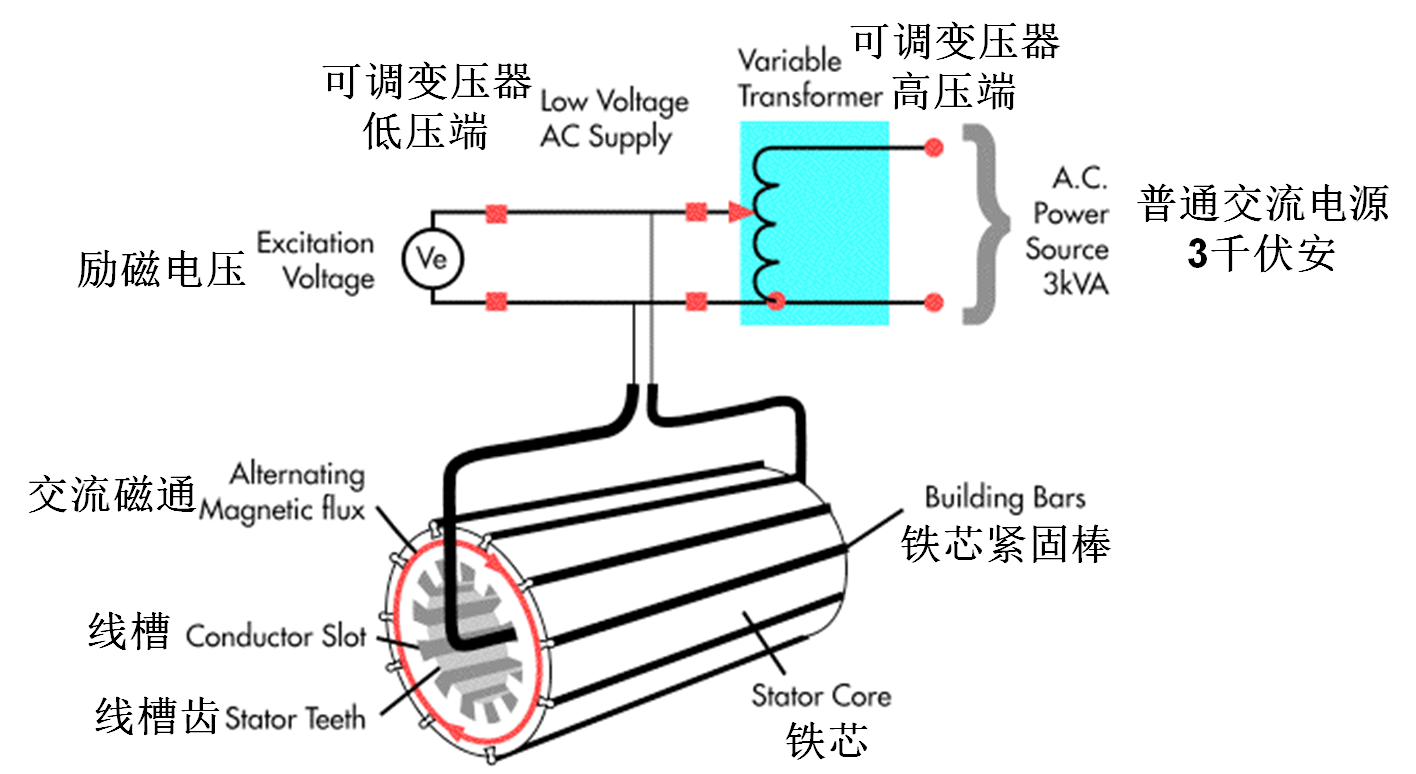
Apart from any large excitationwinding and any associatedautotransformer, the system parts will normally fitwithin a large portable case. EL CID fault current signals are detected by asensor in the
form of a Chattock coil, a longflexible solenoid of fine wire [4] providing an output proportional to themagnetic potential between its two ends in contact with the core surface.
To scan a complete core for faults(a Global Test) the core is divided into a number of strips along its length.Each of the strips is scanned in turn to cover the whole core internal surface.A suitable strip for this purpose is conveniently defined by each slot. By scanningeach slot including the width of both adjacent teeth a degree of overlapbetween scans is achieved which is useful in providing additional informationon fault location.
Fig. 3 shows the location of aChattock sense coil across a slot and tooth pair.
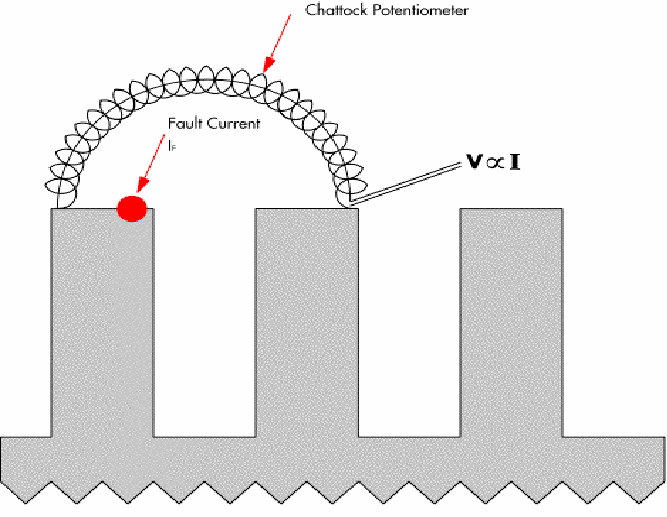
Fig. 3. Chattock coilpositioning on stator core
The magnetic potential acrosseach tooth pair will be comprised of in-phase excitation field (PHASE signal)together with any phase quadrature (QUAD signal) produced by a fault current.
The QUAD signal is separatedfrom the PHASE signal by a phase discriminator in the EL CID signal processorunit. The phase discriminator requires a phase angle reference for the inphase componentand this is provided by a phase pickup coil. This signal may be derived in a numberof ways including from the excitation current, as shown in Fig.2, or backgroundexcitation field within the bore. The stator bore may be scanned by variousmanual or automatic means dependent upon the size and orientation of the coreand whether the rotor is removed as is currently more normal. Test results may advantageously be displayed in the formof a test trace of the amplitude of the QUAD signal against distance along thebore, now more normally displayed on a computer screen and stored on PC media.Similar traces for the PHASE signal vector may yield additional information fortest result interpretation. In a fault free uniformly constructed generator, aslot QUAD trace will theoretically be a straight line along the zero axis and thePHASE trace will be line corresponding to the level of excitation. However inpractice a number of effects may give rise to offsets and perturbations in theQUAD trace and faults will normally be indicated by deviations from a meanlevel. At the standard excitation level of four percent, a threshold of 100mAfault signal is normally taken as a level above which more detailed examinationis required. Although correlation with thermal tests will be dependent upon a numberof factors,
this threshold levelcorresponds approximately to a 5° - 10° C rise in temperature. The correlationfor a number of different faults is given in [2] and [3]. Fault interpretationalso makes use of adjacent slot trace information and a guide to recognition ofcommon faults and locations is provided in [1] which also covers thepossibility of improved detection of faults deeper in the core body by means ofscanning across multiple slots. Polarity of the magnetic potential differencesensed by the Chattock Potentiometer may be used to determine whether thesource of the signal is within the span of the coil. The low voltages used inEL CID testing permit an operator to enter the excited core to perform localtests with small handheld coils to obtain precise location of faults detectedin the Global scan.

IRIS-EL CID Evolution)
Technical advantages
- low excitation energy - 4%, with high sensitivity can detect tiny fault.
- high speed, portable?Don't need other large equipment, in terms of setting and testing instrument
, can significantly shorten the testing time
- low manpower requirements,
- to reduce the subjective judgement of the result of the test
- immediately interpret test results
- automatic and permanent maintain test records.
- test may be repeated during the period of maintenance
- presence of winding can be tested
- can be determined under the surface, wire rods, or under the surface of the fault
- on deep fault detection more effectively
Partial repeat testing - to the core, and to merge the data to obtain a complete pattern of the core status.
Security features
- to use only 120/230 v power excitation and operations
- double insulation to reduce the risk of operating personnel
- low excitation flux levels can reduce further damage for layer insulation, avoid iron core in the absence of the cooling system
testing configuration

Test configuration